
Static mixer pipe
How a flanged static mixer pipe is sized, connected and fitted into your existing pipework, and what we need to quote one.
- Exclusive STRIKO agent Benelux
- ISO 9001 · KIWA
- Engineering support from Monster (NL)
Four steps that repeat in every mixing element.
Split
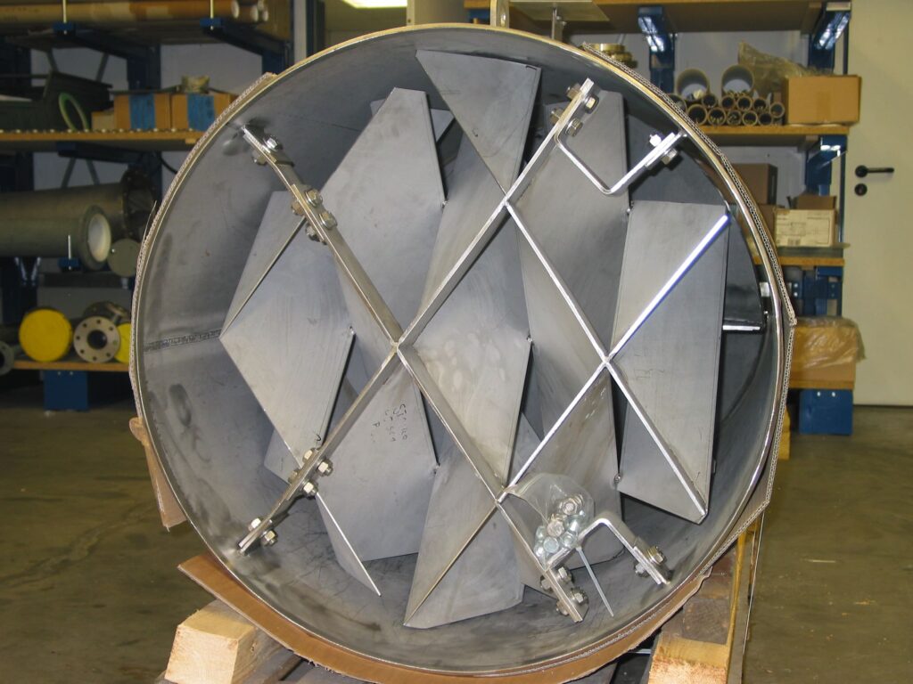
Mixing elements divide the flow into smaller partial streams.
Redirect
The partial streams are redirected, creating shear.
Recombine
The streams merge again, element after element.
Homogeneous
No moving parts, energy taken from the pressure drop.
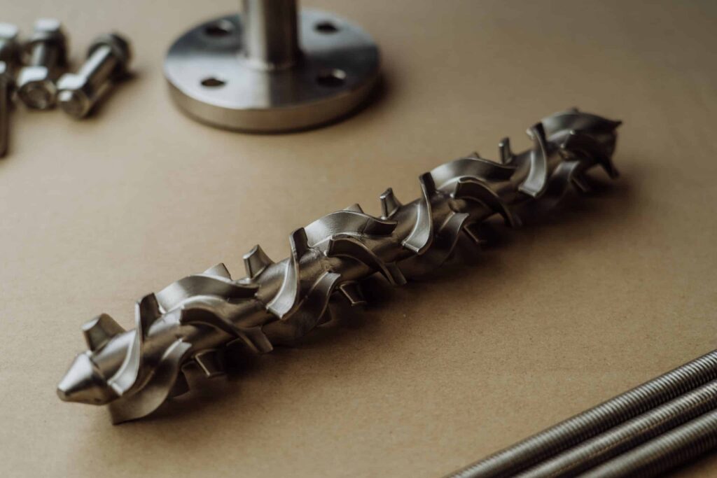
A static mixer pipe is a complete pipe section with flanged ends and fixed mixing elements inside, installed between two flanges in an existing line. Diameter, length and elements are configured to the process, and the pressure drop across the section provides the mixing energy. Dutch Valve Vision supplies STRIKO static mixers as exclusive agent for the Benelux.
- Configurable diameter, length and elements
- Fits into existing pipework
- Easy dismantling for cleaning or inspection
- Mixing energy comes from pressure drop
What a static mixer pipe is: a mixer you bolt into the line
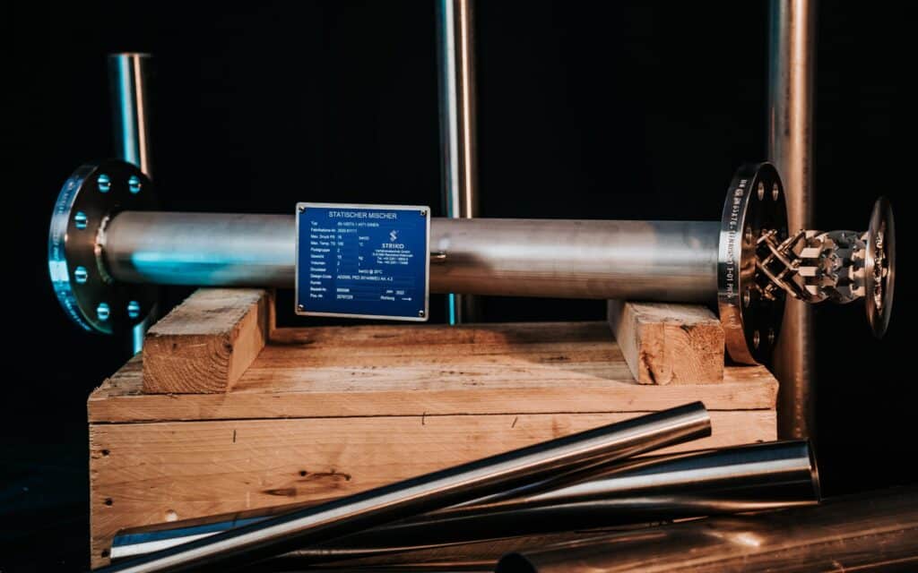
A static mixer pipe is exactly what the name suggests: a section of pipe with flanged ends and a set of fixed mixing elements inside, built to be bolted into a process line like any other spool piece. From the outside it looks almost boring. A length of pipe, two flanges, perhaps a nameplate. The interesting part is invisible, because inside that pipe the elements split the flow, redirect it and recombine it again and again until two separate streams leave as one homogeneous mixture.
That modest appearance is exactly the point. A pipe fitter does not need special tools or a new foundation to install it. There is no motor to wire, no gearbox to align and no control cabinet to modify. The mechanical team treats the static mixer pipe as a pipe section, while the process engineer treats it as a mixing step, and both are right.
At Dutch Valve Vision we are the exclusive agent of STRIKO Verfahrenstechnik GmbH for the Netherlands, Belgium and Luxembourg. STRIKO static mixers are designed for continuous inline operation in closed pipework, and they are configurable in diameter, length and internal elements. This page looks at the static mixer pipe from the installation side: how it is sized, how it connects to your existing flanges, what it does to the pressure profile of the line and how it is inspected once it is in service.
Picture a maintenance planner who receives a request to add a mixing step to a line that has been running for years. There is no room for a tank, the budget for civil works is zero and the shutdown window is short. A flanged mixer section that fits between two existing flanges is often the only realistic answer. The rest of this article is about making sure it actually fits, hydraulically as well as mechanically.
Diameter and length of a static mixer pipe
The two dimensions that define a static mixer pipe are its diameter and its length, and neither of them should be chosen by looking only at the existing line. It is tempting to take the nominal diameter of the pipe the mixer will sit in and simply order a mixer in that size. Sometimes that is correct. Often it is a starting point that needs checking.
The diameter determines the flow velocity through the elements. In turbulent service, velocity drives mixing intensity, so a mixer that is too large for the flow may not mix as vigorously as intended. In laminar service, which is typical for viscous products, the relation is different and the number of splitting and recombining steps matters more than velocity. Diameter also has a direct effect on pressure drop, which we discuss further on. In some cases the best solution is a mixer section one size smaller or larger than the line, connected with reducers. In others the line size works perfectly.
The length follows from the number of elements the process needs. A short section with few elements suits an easy blending task with similar viscosities. A longer section with more elements handles large viscosity ratios, small dosing ratios or components that resist mixing. The flexibility of STRIKO designs in diameter, length and element configuration allows the unit to be matched to the viscosity, flow velocity and end quality the process demands.
In a retrofit, length has a practical side as well. The available space between two existing flanges, or the length of a spool piece that can be removed, sets a limit. If the required mixing length does not fit, there are options, such as a different element type, a different diameter or modifications to the surrounding pipework. The earlier we know the available installation length, the fewer surprises there are during the shutdown.
Flanges and standards: fitting a static mixer pipe into existing pipework
A static mixer pipe has to connect to the plant exactly as any other pipe section does, which means the flanges must match the existing line in standard, size, pressure rating and facing. Dutch Valve Vision supplies to both DIN and ANSI standards, and we see both worlds side by side in many installations.
In European installations built to DIN and EN standards, flanges are specified by nominal diameter DN and pressure rating PN. In installations specified to ASME, flanges are defined by nominal pipe size NPS and a pressure class. The two systems do not mix. A DN flange and an NPS flange of roughly the same size will not bolt together properly, and a mismatch discovered on the day of installation is one of the most avoidable delays in any shutdown. The facing type, bolt pattern and gasket type should also match the adjoining flanges.
Beyond the flange itself, three installation details deserve attention. The first is face to face length, which must fit the gap in the line including gaskets. The second is support. A mixer section in a larger diameter or a heavy material adds weight to the line, and the pipe supports need to carry it without putting load on the flanges. The third is access. Because the elements may have to come out for cleaning or inspection, there should be enough clearance around the section to unbolt it and lift it out.
For the procurement side, the practical advice is simple. Send us the existing line data, including pipe size, flange standard, pressure rating, facing and the available installation length. With that information the static mixer pipe can be designed to drop into place without changes to the surrounding pipework.
Selection starts with four data points
With these we choose series, diameter and number of elements.
Viscosity
Of the main stream and of the added component.
Flow rates
Main flow and dosing, also at part load.
Temperature and pressure
Determine material and allowable pressure drop.
Mixing quality
How homogeneous the product must be downstream.
Pressure drop along a static mixer pipe
Every static mixer pipe causes pressure drop, and that pressure drop is not a side effect but the energy source of the mixing process. As the product passes the elements it loses pressure, and that lost pressure is exactly what performs the splitting, redirecting and recombining. No motor is needed because the pump that already moves the product supplies this energy.
It helps to think of the pressure profile along the line. Upstream of the mixer the pressure falls gradually through normal pipe friction. Across the mixer section the drop is steeper, because the elements create far more resistance than an empty pipe. Downstream the gradual decline continues. The size of that steeper step depends on flow rate, viscosity, diameter and the number and type of elements. In laminar flow it rises roughly in proportion to velocity, while in turbulent flow it rises roughly with the square of the velocity.
For a new line, the pressure drop is simply included in the hydraulic calculation. For a retrofit, it deserves a careful check. A pump that was comfortably sized for the original line may now have to deliver extra head at maximum flow. If the margin is small, the options include a larger mixer diameter, fewer or different elements, or a check of whether the pump can run at a different operating point.
A pressure gauge or transmitter upstream and downstream of the section gives valuable information once the line is in service. A rising differential pressure over time can indicate deposits on the elements, which is a useful trigger for an inspection. Measuring points for mixing quality, together with a pressure test and leak detection, are also part of the validation steps we support after installation.
Specification ready? We will prepare a targeted quote.
Send us medium, pressure, temperature and connection. Our specialists come back with a matching proposal.
Installation, inspection and removal of the mixer section
Because a static mixer pipe has no moving parts, wear is virtually ruled out and regular mechanical maintenance is unnecessary. That does not mean the section is installed and forgotten. Depending on the product, deposits can build up on the elements, and in hygienic applications the elements must be accessible for inspection.
A STRIKO static mixer is designed for easy dismantling when it needs cleaning or inspection. In food, beverage and pharmaceutical lines they also support inline sterilisation and steam cleaning, so they can take part in the normal cleaning cycle without being removed. When a visual inspection is needed, the flanged construction makes it straightforward to take the section out of the line, inspect or clean the elements and put it back.
A few practical habits make that easier. Leave enough room around the section to unbolt and lift it. Keep spare gaskets for the flanges on site. Record the differential pressure after commissioning, so there is a reference value to compare with later. And note the orientation of the section, particularly in lines where drainability matters for hygiene.
Upstream and downstream: the pipework around the mixer section
A mixer section performs only as well as the pipework around it allows. Two locations deserve extra attention on the drawing: the dosing point upstream and the measuring point downstream.
Upstream, the added component should enter the elements quickly. If a dosing nozzle sits a long way before the section, the dosed stream has time to settle along the pipe wall or to form a separate layer, especially in laminar flow with viscous products. Placing the dosing point shortly before the section avoids that. The way the component is introduced matters too. A nozzle that brings the additive towards the centre of the pipe gives the elements a better starting position than a simple connection at the wall. When the dosing pump stops, a check valve in its line keeps process medium from flowing back.
Downstream, the question is where to prove that the mixture is homogeneous. A sampling point or an inline analyser directly after the last element shows the result of the mixing step itself. Further downstream, bends, valves and other fittings add their own disturbance, which can help or complicate interpretation. We advise on a sensible position as part of the validation plan.
Orientation is the last point on the drawing. Many lines are horizontal, others vertical, and the medium determines whether that matters. Where gas and liquid flow together, or where the product must drain completely for hygienic reasons, the orientation of the section is part of the design rather than a matter of convenience. We ask about it early so the section fits the intended layout.
Materials for the pipe body and the elements
The material of a static mixer pipe is chosen on the same basis as the rest of the line: the medium, the temperature, the pressure and any corrosive conditions. Most often that means stainless steel, for example SS316, 1.4404 or 1.4571. Carbon steel suits less demanding media. Plastics such as PVC, PE and PVDF are widely used in water treatment and chemical dosing lines. For aggressive media, special coatings or linings are available, and materials can be adapted to project-specific requirements.
The body and the elements see the same medium, but not always the same conditions. Where a concentrated chemical is dosed just upstream of the section, the first elements meet it before it has been diluted. That is worth considering when the material is selected. In plastic dosing lines, where the adjoining pipework is PVC, PE or PVDF, a mixer section in the same material family keeps chemical resistance consistent along the whole line and avoids a weak spot at exactly the point where the chemical is most concentrated. In stainless steel lines, the grade of the mixer section should at least match the grade of the pipework it joins.
Ordering a static mixer pipe from Dutch Valve Vision
To design a static mixer pipe that fits both the process and the pipework, we need two sets of data. The process set covers the viscosity of each component, the volume flows at minimum and maximum load, temperature, pressure and the mixing quality required at the outlet. The mechanical set covers pipe size, flange standard, pressure rating, facing, available installation length and material requirements. With both, we select the STRIKO series, EREstat for hygienic food processes, Helical as the universal mixer, STV for gases or STX for viscous liquids, and configure diameter, length and elements.
Our ISO 9001 quality management system is certified by KIWA, and the team in Monster, the Netherlands, handles your enquiry directly. Mail the line and process data to sales@dutchvalvevision.com, or phone +31 (0)70-2210560 on weekdays between 09:00 and 17:00.
Frequently asked questions about static mixer pipe
Can a static mixer pipe replace an existing pipe spool?
Yes, that is one of the most common ways to add a mixing step to an existing line. The mixer section is designed with flanges that match the adjoining pipework. Its face to face length is matched to the gap left by the removed spool, including gaskets. The pressure drop of the new section must be checked against the existing pump. Pipe supports should be able to carry the weight of the section. Dosing points may need to be moved closer to the mixer to get the full benefit. We need the existing line data and the available installation length to design it properly. With that information the section can be installed during a short shutdown.
Which flange standards are possible for a static mixer pipe?
Dutch Valve Vision supplies to both DIN and ANSI standards. In DIN and EN installations flanges are specified by DN and PN rating. In ASME installations they are defined by NPS and pressure class. The flanges of the mixer section are matched to the standard of your line. Facing type and bolt pattern must also match the adjoining flanges. A mismatch between systems is one of the most avoidable causes of delay during installation. Please state the standard, size, rating and facing in your request. That way the section arrives ready to bolt in.
How long does a static mixer pipe need to be?
The length follows from the number of elements the process requires. An easy blending task with similar viscosities needs relatively few elements. Large viscosity differences, small dosing ratios or components that resist mixing need more. The flow regime also plays a role, because laminar and turbulent mixing work differently. In a retrofit the available installation length sets a practical limit. If the required length does not fit, a different element type or diameter can sometimes solve the problem. We determine the length on the basis of your process data. Tell us the available space from the start to avoid redesign later.
Does the diameter of the mixer have to match the pipe?
Not necessarily, although it often does. The diameter determines the flow velocity through the elements, which affects both mixing intensity and pressure drop. In turbulent service a mixer that is too large for the flow may not mix vigorously enough. A smaller diameter mixes more intensively but increases the pressure drop. In some cases a section one size different from the line, connected with reducers, gives the best result. The choice depends on flow rate, viscosity and the available pressure. We check this during selection. You will receive a proposal that states the diameter and the reasoning behind it.
What pressure drop should I expect across a static mixer pipe?
That depends on flow rate, viscosity, diameter and the number and type of elements. For laminar flow, pressure drop grows about linearly with velocity. With turbulent flow the rise is much steeper, close to the square of the velocity. Viscous products at high flow cause considerably more pressure drop than thin liquids. The pressure drop is the energy that drives the mixing, so some drop is always required. The question is whether the pump can deliver it at maximum flow. We calculate the expected value for your conditions. Pressure measurement before and after the section helps you track it once the line is in service.
Can the elements be removed from a static mixer pipe?
Taking a STRIKO mixer apart for cleaning or inspection is a simple job. The flanged construction also makes it straightforward to take the whole section out of the line. In hygienic applications the mixer supports inline sterilisation and steam cleaning, so removal is not needed for routine cleaning. For visual inspection or thorough cleaning after a product with deposits, removal is the practical route. Leave enough clearance around the section to unbolt and lift it. Keep spare gaskets available for reassembly. A rising differential pressure over time is a useful signal that an inspection is due. We are happy to advise on a sensible inspection interval for your medium.
How is a static mixer pipe tested after installation?
Validation typically starts with a pressure test and leak detection on the installed section and its flanged connections. After that, the process side is checked. Measuring points for mixing quality downstream of the section show whether the required homogeneity is achieved. Simulations of flow velocity and homogeneity can support the design and the interpretation of results. Recording the differential pressure at commissioning gives a reference for later comparison. If the results deviate from expectations, the cause is usually found in dosing position or flow conditions. We support installation, validation and optimisation. That way the section performs as intended from the first day.
What information does Dutch Valve Vision need to quote a static mixer pipe?
We need process data and mechanical data. On the process side, that is the viscosity of each component, the minimum and maximum flows, temperature, pressure and required mixing quality. On the mechanical side, it is pipe size, flange standard, pressure rating, facing and the available installation length. Material requirements and the chemical composition of the media determine the construction material. A sketch or P&ID showing dosing points helps us advise on positioning. With these data we select the STRIKO series and configure the section. Send your request to sales@dutchvalvevision.com or call +31 (0)70-2210560. We will get back to you as soon as possible.
Get a static mixer pipe that fits your line
Send us pipe size, flange standard and pressure class, available installation length, flows, viscosities, temperature and pressure. We will propose a matching STRIKO mixer section.
- +31 (0)70-2210560
- sales@dutchvalvevision.com
- Vlotlaan 641, 2681 TZ Monster, the Netherlands
- Mon-Fri 09:00-17:00