

Automatic recirculation valve
Why one self-actuated automatic recirculation valve can replace a complete minimum flow control loop, and what that means for your costs.
- Exclusive Schroeder Valves agent Benelux
- Original spare parts
- ISO 9001 · KIWA
Exclusive agent for Schroeder Valves
Official spare parts distributor
Quality system, KIWA certified
Service and advice from the Netherlands
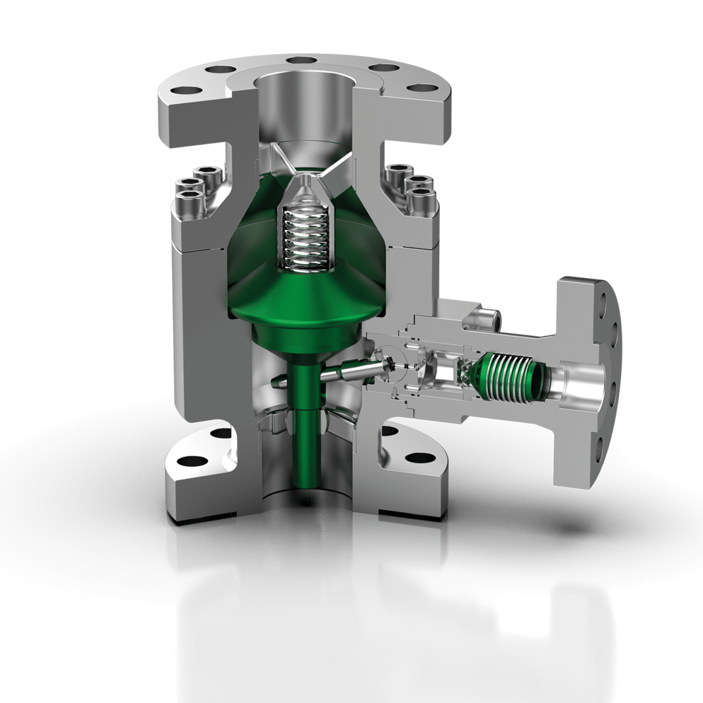
How an automatic recirculation valve works
One valve that adjusts itself to process demand.
Full load
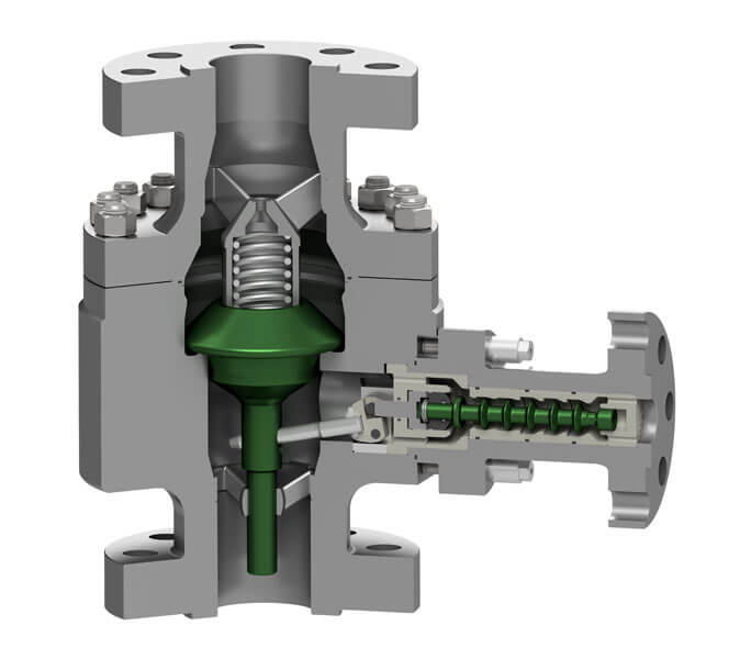
The disc is open in the main flow. The bypass stays closed, no energy is lost.
Part load
As demand drops the disc moves down and the mechanically linked bypass opens.
Zero load
The minimum flow returns through the bypass. The pump stays protected, without external energy.
Why the automatic recirculation valve keeps winning on the drawing board
An automatic recirculation valve does in one valve body what many plants still do with four or five separate components, and that is exactly why engineers start asking questions when they see the conventional alternative on a P&ID. Picture a process engineer drawing the discharge side of a new pump. First comes a check valve. Then a flow element with a transmitter, because the control system needs to know whether the pump is running above its minimum flow. A branch line leaves the discharge, with a control valve in it, often with isolation valves on both sides and a pressure reducing device behind it. The transmitter reports to a controller in the DCS, the controller sends a signal to the positioner, and the actuator needs instrument air. Every single item gets a tag number, a data sheet, a spare parts list and a place in the maintenance plan.
Now picture the same drawing with a Schroeder automatic recirculation valve. One valve on the pump discharge, one outlet to the process and one bypass outlet to the return line. That is it. No cabling to the valve, no air supply, no loop to tune.
At Dutch Valve Vision we are the official and exclusive agent of Schroeder Valves for the Benelux, and this comparison is the natural starting point in conversations with engineering firms and plant owners. Schroeder has built these valves for more than 70 years. The idea is not new, but the arguments for it have only become stronger as plants try to reduce complexity, maintenance hours and energy consumption at the same time.
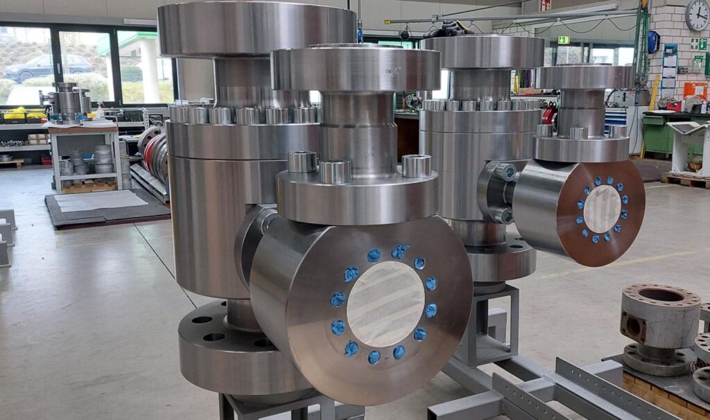
The conventional minimum flow loop, component by component
To judge an automatic recirculation valve fairly, you first need to look honestly at what it replaces. The conventional minimum flow system is not a bad design. It is simply a long chain of parts that all have to work at the same moment.
Flow measurement
The loop starts with a flow meter in the pump discharge. It needs a suitable straight run of pipe, it has to be calibrated, and its signal is only as good as its installation. Deposits, gas bubbles or a drifting transmitter all lead to a wrong reading. A wrong reading in a minimum flow loop means one of two things: either the bypass opens when it is not needed and wastes energy, or it stays closed when the pump really needs it.
The controller and the control system
The flow signal goes to a controller, usually a function block in the DCS or PLC. Somebody has to configure it, tune it and keep it documented. Input cards, cabling, junction boxes and power supplies are all part of the chain. A software change elsewhere in the system can affect the loop without anybody noticing until the pump starts to suffer.
The recirculation control valve
The control valve in the bypass line has one of the hardest jobs in the plant. It sees the full difference between pump discharge pressure and the pressure at the return point, often in a single stage. That is a recipe for trim erosion, noise and cavitation. The valve needs a positioner, an actuator and instrument air, and it usually needs periodic overhaul.
The separate check valve
Finally there is the check valve in the main line, which prevents reverse flow when the pump stops. It is one more item with flanges, gaskets and inspection intervals.
Schroeder ARC series at a glance
A dedicated series for every pressure class and application.
An automatic recirculation valve protects a centrifugal pump by combining a check valve and a minimum flow bypass in one self-actuated body. It replaces the classic loop of flow meter, controller, control valve and separate check valve, so there are fewer failure points and no need for power, instrument air or control software. That lowers both investment and maintenance costs over the life of the installation.

Schroeder SSV
Standard, compact all-in-one design.
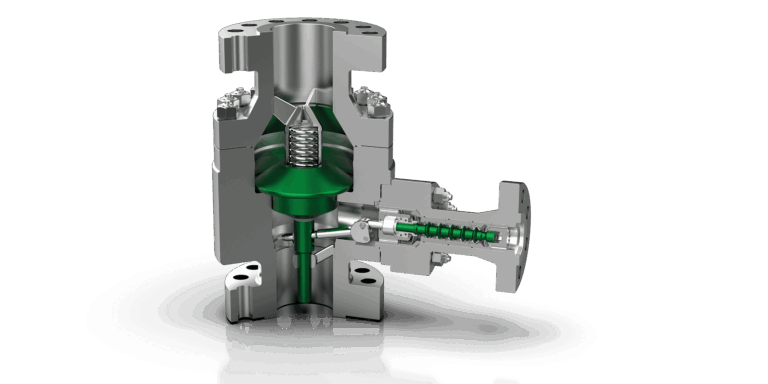
Schroeder SIP
Medium pressure, up to about 250 bar.
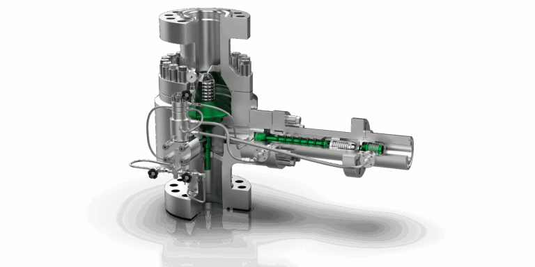
Schroeder SHP
High and very high pressure.

Schroeder SMA
ON/OFF, pilot operated.
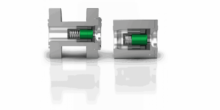
Schroeder SDV
Back pressure device with check function.

Schroeder SSD
Multi-stage throttle for high differential pressure.
What a single automatic recirculation valve does instead
An automatic recirculation valve merges these functions into one mechanical system. In the main line sits a check disc that is lifted by the pump flow. The position of that disc tells the valve exactly how much the process is taking. The disc is mechanically coupled to the bypass. When process flow drops, the disc moves towards its seat and the bypass opens. When process flow rises, the disc lifts and the bypass closes. When the pump stops, the disc closes and prevents reverse flow.
The flow itself is the sensor, the disc is the controller and the coupling is the actuator. There is no separate measurement, no separate logic and no separate final element. The valve reacts directly to changes in flow, without oscillation or instability in the system, because there is no signal delay and no controller that has to be tuned. It works without electrical power, sensors or external control, and responds only to the hydraulic conditions in the system.
The bypass reduces the pressure in a controlled way, often in several stages in high pressure designs. That solves the problem that makes a single stage control valve suffer so much. For extreme pressure differences Schroeder adds SSD multi-stage throttle valves, designed for controlled pressure and flow reduction in erosion sensitive services.
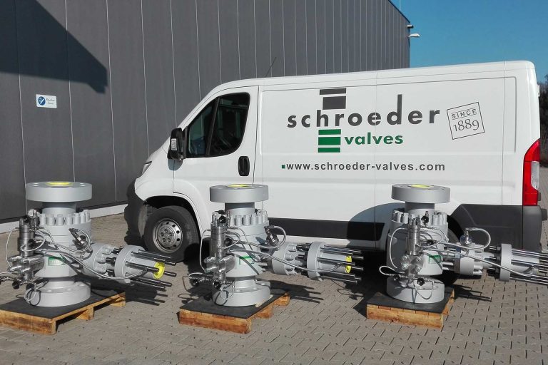
Counting the failure points
Engineers who work on reliability think in failure chains, and that is where the automatic recirculation valve makes its strongest case. In the conventional loop, the pump is only protected when every link does its job. The flow element must measure correctly, the transmitter must be powered and calibrated, the input card and controller must work, the output signal must reach the positioner, the instrument air must be available and the control valve must move freely. The check valve in the main line must close when the pump stops. A failure in any one of those elements can leave the pump running against a closed system without protection.
Think of a situation every maintenance team recognises. A plant loses instrument air for a short period, or a power dip resets part of the control system. The main process valves fail to their safe position and the pump suddenly sees very little demand. In the conventional setup, that is exactly the moment when the recirculation control valve may not be able to respond as intended. With a self-actuated valve, the protection continues as if nothing happened, because it never depended on air or power in the first place.
Fewer components mean fewer failure points. That sentence sounds obvious, yet in practice it is often overlooked when a design is copied from a previous project. We encourage engineers to count the tag numbers in their minimum flow system and ask which of them are really needed to protect the pump.
Service and overhaul
OEM
Only original Schroeder parts.
Test bench
Flow calibration and pressure test after overhaul.
Warranty
Full Schroeder factory warranty.
Total cost of ownership: where the savings come from
An automatic recirculation valve is sometimes seen as an extra component, while in reality it lowers system costs over the life of the installation. The savings come from several directions at once.
On the investment side, one valve replaces a check valve, a control valve with actuator and positioner, a flow meter, the cabling, the air supply and the engineering hours for the loop. There are fewer flanges, less piping in the bypass arrangement and less work during commissioning. Loop checks, configuration and documentation shrink as well.
On the operating side, there is no transmitter to calibrate and no control valve trim to replace after erosion. The spare parts list becomes shorter, and the maintenance plan contains one item instead of several. Because the pump is kept in its safe operating range at all times, wear on the pump itself goes down, and so do repairs and unplanned downtime.
Then there is energy. Plants that protect their pumps with a fixed continuous bypass pay for that recirculation every hour of the day, even at full load. An automatic recirculation valve only recirculates when the process flow is too low, and closes the bypass when the process takes enough. Over years of operation, that difference adds up.
We are careful not to put numbers on these savings without your data, because they depend on your pump, your operating profile and your maintenance organisation. What we can do is walk through your current loop with you and list, component by component, what disappears and what remains.
Retrofitting an automatic recirculation valve in an existing plant
Replacement projects typically start with a pump that has caused trouble. A recirculation control valve that keeps eroding, a flow transmitter that drifts, or a pump that has needed new bearings and seals more often than expected. The question then becomes whether the whole loop can be simplified at the next turnaround.
The first step is a survey of the existing situation. We look at the pump data and the minimum flow required by the pump manufacturer, the normal and maximum process flow, the medium and temperature, and the pressure at the return point. We also look at the physical layout: where the current check valve sits, how the bypass line runs and where it ends. In many cases the existing return line can be reused, while the control valve, its actuator and the flow loop are removed.
Some owners choose to keep a flow measurement for monitoring purposes only. That is perfectly possible, as long as the protection no longer depends on it. The automatic recirculation valve then does the protecting, and the measurement simply informs the operator.
There are situations where a plant has good reasons to keep a controlled loop, for example because of a specific company standard. We discuss that openly. Our job is to give you a well founded choice, not to sell a valve at any price.
Specification ready? We will prepare a targeted quote.
Send us medium, pressure, temperature and connection. Our specialists come back with a matching proposal.
Designing an automatic recirculation valve into a new project
In a new project the biggest gains are made early, before the P&ID is frozen and before the instrument index has grown. The earlier the automatic recirculation valve is chosen, the more tags, cables and loop diagrams never have to be created in the first place.
The starting point is the pump. The pump manufacturer defines the minimum flow, and that value has to be agreed before the valve can be sized. We see projects where the pump is still being selected while the piping layout is already progressing. In that case it pays to reserve space for the valve directly on the pump discharge and to route the return line with the final minimum flow still open. Once the pump data are fixed, the bypass can be sized exactly.
The return point deserves attention too. The recirculated liquid picks up heat in the pump, so it is usually sent back to a suction vessel, tank or deaerator where that heat can dissipate, rather than straight into the pump suction. The pressure at that point determines how much pressure the bypass has to reduce, and therefore whether a standard design is enough or a multi-stage solution is needed.
Installations with parallel pumps need their own logic. When two pumps run together at low demand, the stronger one can push the weaker one back towards its shut-off point. Giving each pump its own automatic recirculation valve keeps every pump protected on its own terms, independent of what the others are doing. That is a design choice we always raise when we see pumps working in parallel on a common header.
Choosing the right Schroeder series with Dutch Valve Vision
Once the decision is made, the series selection follows from pressure, flow ratio and application. The SSV series is the standard, compact all-in-one valve for general industrial use, power plants and process installations. The SSV with control disc covers a high minimum flow of up to about 70 percent of the main flow. Feed water and utility pumps up to about 250 bar are the territory of the SIP series. The SHP series covers high and very high pressure with strongly fluctuating loads, and the SMA series offers pilot operated ON/OFF minimum flow control at very high pressure. SDV back pressure devices and SSD multi-stage throttle valves complete the picture where extra pressure control is required.
Dutch Valve Vision supports you from the first comparison to installation and after-sales. We work with an ISO 9001 certified quality management system, certified by KIWA, and supply to DIN and ANSI standards. For existing Schroeder valves we deliver original spare parts, and repairs are carried out with OEM parts, followed by a flow calibration test, a pressure test on the Schroeder test bench and a full factory warranty.
Would you like us to review your current minimum flow loop? Call us on +31 (0)70-2210560 or email sales@dutchvalvevision.com. We are available Monday to Friday from 09:00 to 17:00 in Monster, the Netherlands.
Frequently asked questions about automatic recirculation valve
Question not listed? Our specialists are happy to help.
- +31 (0)70-2210560
- sales@dutchvalvevision.com
- Vlotlaan 641, 2681 TZ Monster, the Netherlands
- Mon-Fri 09:00-17:00
What is an automatic recirculation valve?
An automatic recirculation valve is a self-actuated valve that protects a centrifugal pump against running at too low a flow. It is installed on the pump discharge and combines a check valve with a minimum flow bypass. When the process demand drops, the bypass opens and sends the required minimum flow back to a tank or suction vessel. When the process demand rises, the bypass closes again. When the pump stops, the check function prevents reverse flow. All of this happens without electrical power, sensors or an external control system. The energy it needs comes from the pumped liquid itself. The product is also known as ARC valve, ARV, minimum flow valve or pump protection valve.
How does it differ from a control valve based minimum flow system?
A conventional system uses a flow meter, a controller, a control valve in the bypass and a separate check valve. Each of those components needs power, air, configuration or calibration. An automatic recirculation valve integrates the measurement, the control and the check function in one mechanical unit. The check disc senses the flow and operates the bypass directly through a mechanical coupling. There is no signal delay and no loop to tune. That makes the valve simpler to engineer and to maintain. It also keeps working when power or instrument air is lost. The result is fewer components and fewer failure points.
Does an automatic recirculation valve react fast enough?
Yes, the valve reacts directly to changes in flow. The check disc moves as soon as the process flow changes, and the bypass follows through the mechanical coupling. There is no transmitter that has to measure first and no controller that has to calculate a response. That is why the valve works without oscillation or instability in the system. This matters during start-up, during sudden load changes and when the pump trips. A conventional loop depends on its tuning and on the speed of the actuator. The self-actuated principle removes those variables. For very high pressure, the pilot operated SMA series offers fast and reliable ON/OFF control.
Which components does an automatic recirculation valve replace?
In a typical installation it replaces the separate check valve in the pump discharge. It also replaces the recirculation control valve with its actuator and positioner. The flow meter and transmitter that were only there for pump protection are no longer needed. The controller function in the DCS or PLC disappears as well. So do the cabling, the instrument air supply and the related loop documentation. Often the isolation valves around the old control valve can go too. The same applies to the pressure reducing orifice that sometimes sits behind it. What remains is one valve body with a main outlet and a bypass outlet.
Does an automatic recirculation valve lower total cost of ownership?
In most cases it does, because fewer components mean lower investment and maintenance costs. There is less engineering, less cabling, less piping and less commissioning work. During operation there is nothing to calibrate and no control valve trim that erodes in the bypass. The pump itself suffers less wear because it always stays above its minimum flow. That reduces repairs and unplanned downtime. Energy use can also drop compared to a fixed continuous bypass. The exact savings depend on your installation and operating profile. We are happy to go through your situation and make the comparison concrete.
Can an automatic recirculation valve be retrofitted into an existing plant?
Yes, we support retrofits in existing plants from start to finish. We start with the pump data, the minimum flow, the process flows and the pressure at the return point. Then we look at the layout of the current check valve and bypass line. In many cases the existing return line can be reused. The control valve, flow loop and separate check valve are then removed. A turnaround or planned maintenance stop is usually the best moment for the change. Some owners keep a flow measurement for monitoring only. We help you plan the retrofit so the downtime stays as short as possible.
Can I keep my flow transmitter after switching?
Yes, you can keep a flow transmitter if you want to monitor the pump. The difference is that the protection no longer depends on that signal. The automatic recirculation valve protects the pump mechanically, whatever the transmitter reports. The measurement then becomes purely informative for operators and maintenance. Some plants use it to follow the operating profile of the pump over time. Others remove it to reduce maintenance. Both choices are valid and depend on your monitoring philosophy. We discuss this with you during the design of the retrofit.
What information does Dutch Valve Vision need to advise?
We start with the pump data and the minimum flow required by the pump manufacturer. We also need the normal and maximum process flow. The medium, its temperature and the operating pressure are essential. The pressure at the point where the bypass returns determines how much pressure the bypass has to reduce. A sketch or P&ID of the current loop helps us see what can be removed. We also want to know the connection standard, DIN or ANSI. With that information we select the right Schroeder series. You can reach us at sales@dutchvalvevision.com or +31 (0)70-2210560.
Replace your minimum flow loop
Send us the pump data, the minimum flow and a sketch or P&ID of your current recirculation loop. We will tell you which Schroeder series can take its place.
- +31 (0)70-2210560
- sales@dutchvalvevision.com
- Vlotlaan 641, 2681 TZ Monster, the Netherlands
- Mon-Fri 09:00-17:00