
Rupture disc relief valve
Why a rupture disc upstream of a relief valve is one of the most used arrangements in pressure safety, and how to design it properly.

In a rupture disc relief valve combination the disc sits directly upstream of the relief valve. The disc keeps the valve isolated from corrosive or fouling media and makes the relief path leak tight, while the valve recloses after an event and limits the loss of medium. The space between the two must be monitored, because trapped pressure raises the pressure at which the disc opens.
- Why the rupture disc relief valve combination is so common
- Reason one: a leak tight barrier in front of the valve seat
- Reason two: keeping aggressive media away from the relief valve
- Designing the space between disc and valve
- Matching burst pressure, set pressure and capacity
- Monitoring the rupture disc relief valve assembly as a whole
- Where the rupture disc relief valve arrangement pays off
- The disc side of your rupture disc relief valve combination from Dutch Valve Vision
Unsure about the right choice?
Share your process data with our specialists. We check the numbers with you and give reasoned advice.
Why the rupture disc relief valve combination is so common
A rupture disc relief valve combination puts two very different devices in series on the same relief branch, and the result is better than either one on its own. The disc sits directly upstream of the valve, between the protected equipment and the valve inlet. During normal operation the disc seals the relief path completely and the valve never touches the process medium. When the pressure reaches the burst pressure, the disc opens, the valve lifts and relieves the excess, and once the pressure has dropped the valve closes again. The disc has done its job once, the valve has done its job and can do it again.
Why go to the trouble of two devices? Because each one covers the weak spot of the other. A relief valve can reclose, but it has a seat that can leak and moving parts that suffer from corrosion and deposits. A rupture disc is 100% leak tight until it bursts and has no moving parts, but it cannot reclose. Put the disc in front of the valve and you get a leak tight barrier during normal operation plus a device that limits the loss of medium after an event. That logic is why this arrangement is one of the most widely used in pressure safety.
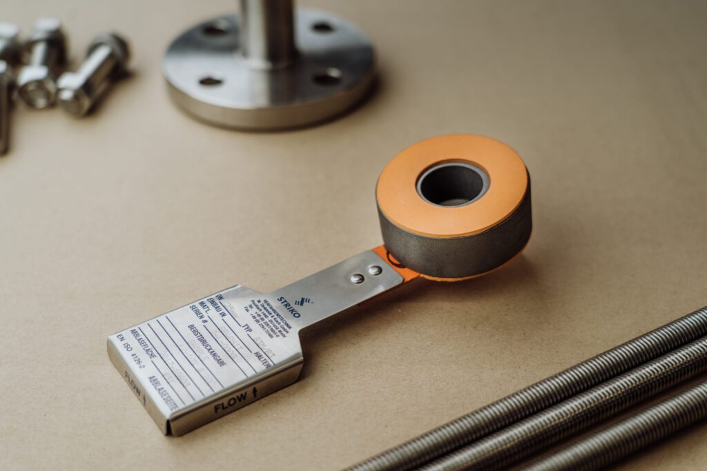
At Dutch Valve Vision we supply the disc side of the rupture disc relief valve arrangement: STRIKO rupture discs, holders and burst detection, selected to fit the valve that is already specified or installed. On this page we look at the arrangement from the designer’s point of view: why it is chosen, how the space between disc and valve should be designed and how the whole assembly is monitored. The day-to-day perspective of the valve owner is covered on our separate page about the safety valve with a rupture disc.
Reason one: a leak tight barrier in front of the valve seat
A spring loaded relief valve relies on a disc pressed onto a seat. That seat is a sealing surface under constant load, and it can show small leaks before the valve opens, especially when the plant runs close to the set pressure or when the seat has worn. For many media that is tolerable. For toxic, expensive or environmentally harmful media it is not.
Placing a rupture disc under the valve solves this at the source. An intact disc is a closed metal or graphite barrier with no seat and no gap. Nothing passes until the disc actually bursts, so the relief path is leak tight during normal operation, however long the valve has been in service. Picture a storage tank for a toxic chemical where every emission counts. With a rupture disc relief valve arrangement, the tank breathes only through its normal vents, and the relief branch stays sealed until it is genuinely needed.
The same barrier also prevents product losses. For expensive media, a slowly weeping valve seat is money leaving the plant through the flare or vent header. A disc upstream of the valve stops that completely, and a burst detection sensor tells you the moment the barrier has opened.
Reason two: keeping aggressive media away from the relief valve
The second reason is protection of the valve itself. Corrosive media attack the seat, the disc and the guiding of a relief valve. Sticky or polymerising media build up on those same parts until the valve no longer lifts at the intended pressure or no longer closes properly. Both problems are hard to see from the outside and both undermine the device you are relying on.
In a rupture disc relief valve arrangement, only the disc and the wetted part of its holder see the process medium during normal operation. The valve sits behind the disc in a clean, dry and unpressurised space. That changes the material question considerably. The disc can be made in a material that suits the medium, from our standard 316 stainless steel to Hastelloy and titanium, or in graphite, which is naturally resistant to many acids, bases and aggressive media without any coating. Holders are available in carbon steel, 316/316L stainless steel, duplex, super duplex, Inconel and Hastelloy. The valve itself is shielded from the medium for as long as the disc is intact.
Think of a chemical plant where a reactor handles an acid that would attack a standard valve within a short time. Rather than specifying every relief valve in an exotic alloy, the engineer puts a corrosion resistant disc in front of each valve. The disc handles the chemistry, the valve handles the reclosing, and the maintenance team is no longer confronted with seized or corroded valve internals at every turnaround.
Designing the space between disc and valve
The short piece of pipe or the cavity between the outlet of the disc holder and the inlet of the valve is where most of the design attention goes. It looks trivial on a drawing. It is not.
Why pressure in the interspace matters
A rupture disc responds to the pressure difference across it, not to the absolute pressure on its process side. If pressure builds up in the interspace, the disc will only burst when the process pressure exceeds the burst pressure plus the pressure trapped behind it. A pinhole leak in the disc, a leaking seal or a temperature change of gas trapped in the cavity can all cause that build-up. The result is that the protected equipment can reach a higher pressure than intended before anything opens. That is why the interspace in a rupture disc relief valve arrangement must be kept at or near atmospheric pressure and must be monitored.
Keeping it short and clean
The disc is normally mounted as close to the valve inlet as the design allows. A short, close coupled interspace keeps the trapped volume small and limits the extra flow resistance in front of the valve. The disc must also open fully and must not release fragments that could lodge in the valve seat or block the valve inlet. The opening pattern of the disc is therefore part of the selection, and domed discs with an X or C scored dome are designed to give a defined opening pattern. We check the design of the disc against its position under the valve before we recommend it.
Monitoring points
The interspace needs a connection for monitoring. Holders can be supplied with leak detection ports where required, which gives a clean connection point without extra fittings in the relief path. On that connection the plant can mount a pressure gauge, a pressure switch or transmitter with an alarm, or a vent through an excess flow valve, depending on the medium and the monitoring philosophy of the site. The exact choice is usually set by the applicable code and the owner’s standards.
Disc isolates the valve from the medium
Holders with leak detection ports available
Burst detection to PLC, SCADA or DCS
Exclusive STRIKO agent for the Benelux
Matching burst pressure, set pressure and capacity
A disc and a valve in series must be coordinated so that they act as one device. The burst pressure of the disc and the set pressure of the valve are chosen together, within the limits of the protected equipment, so that the disc opens reliably before or at the point where the valve is meant to lift. Both values depend on temperature. At higher temperatures the effective burst pressure of a disc can fall, depending on material and design, so the temperature in the relief scenario is part of the calculation. The tolerance around the burst pressure, determined by material properties and the manufacturing process, is taken into account as well.
Capacity needs a check too. The disc and its holder add flow resistance in front of the valve, and the relief capacity of the combination is therefore not simply the capacity of the valve. Design codes contain rules for rating such combinations, and a valve with a disc in front of it must still relieve the required flow while operating stably. This is one reason why we always ask for the valve data when a customer requests a disc for this position.
Operating ratio completes the picture. The relation between the maximum operating pressure and the burst pressure directly affects the service life of the disc. A disc that runs close to its burst pressure day after day, or sees strong pressure cycles, will fatigue sooner. Reverse buckling holders offer higher resistance to pressure cycles, better performance at high temperatures and a lower risk of fatigue, which makes reverse acting designs a frequent candidate for the rupture disc relief valve position on cycling processes.
Monitoring the rupture disc relief valve assembly as a whole
Two things need watching: whether the disc has opened, and whether the interspace is still at atmospheric pressure. The first is the task of a burst detection sensor. Electrical detection monitors a loop that is interrupted when the disc breaks, and magnetic detection reads a field that changes when the disc moves. Fail-safe designs also report a defect in the sensor itself, so a false negative is avoided. The signal can go to PLC, SCADA or DCS, and detection can be applied in ATEX zones.
The second task belongs to the interspace instrument described above. Together they give a complete picture. A burst signal tells the operator that the valve is now exposed to the process medium and that a replacement disc is needed. A rising interspace pressure without a burst signal tells the operator that the disc may be leaking and that the relief pressure of the system may have shifted. Both are reasons to act, and both are invisible without monitoring.
Where the rupture disc relief valve arrangement pays off
The arrangement earns its place wherever leak tightness and valve protection matter at the same time. Chemical and petrochemical plants use it on reactors, columns and storage vessels with toxic or corrosive media. Installations with expensive media use it to prevent product loss through valve seats. Hydrogen and ammonia installations, where material choice and process safety are critical, use disc based protection as part of a carefully designed relief concept. In hygienic processes, an aseptic disc with a highly polished surface can keep product away from a valve that would otherwise be difficult to clean.
It is less suitable where the relief device is expected to act often, because every activation means replacing the disc. In that case the combination still works, but the logistics of spare discs and the process interruption after each event need to be weighed carefully.
The arrangement is also a common retrofit. Imagine a relief valve on an existing vessel that has been overhauled several times because of a leaking or corroded seat, each time at the next turnaround. Adding a disc in front of that valve can end the cycle, provided the available space, the valve inlet losses and the relief capacity allow it. A retrofit rupture disc relief valve assembly therefore starts with the same questions as a new one, plus a close look at the dimensions of the existing branch.
The disc side of your rupture disc relief valve combination from Dutch Valve Vision
Dutch Valve Vision, based in Monster in the Netherlands, is the exclusive agent of STRIKO Verfahrenstechnik GmbH for the Netherlands, Belgium and Luxembourg. STRIKO has been active in rupture discs since 1974 and works to a philosophy of testing, evaluating and recalibrating. For the rupture disc relief valve position we supply the disc, the holder with optional leak detection port and the burst detection. Our holders are designed in line with ASME Section VIII, EN ISO 4126 and PED 2014/68/EU, and ATEX where applicable, with material certificates to EN 10204 3.1, pressure calculations, inspection reports and traceability per component. Engineering support includes selection of the disc and holder combination, FEM analyses on request and support in HAZOP and other safety studies.
To select the right disc we need the medium and its composition, the operating pressure including peaks, the set pressure and the data of the relief valve, the temperature in normal operation and in the relief scenario, the connection and the space available between equipment and valve. Our sales team is reachable at sales@dutchvalvevision.com and on +31 (0)70-2210560, Monday to Friday from 09:00 to 17:00.
Specification ready? We will prepare a targeted quote.
Send us medium, pressure, temperature and connection. Our specialists come back with a matching proposal.
Frequently asked questions about rupture disc relief valve
Question not listed? Our specialists are happy to help.
Why install a rupture disc upstream of a relief valve?
There are two main reasons, leak tightness and protection of the valve. An intact rupture disc is 100% leak tight, while a relief valve can leak slightly at its seat before it opens. With the disc in front of it, the relief path stays sealed during normal operation. The disc also keeps corrosive, sticky or polymerising media away from the valve seat and internals. That protects the valve against corrosion and deposits that could stop it from lifting or closing properly. After an event, the valve can still reclose and limit the loss of medium. The combination therefore offers the strengths of both devices. It is one of the most widely used arrangements in pressure safety.
Why must the space between disc and relief valve be monitored?
A rupture disc responds to the pressure difference across it. If pressure builds up in the space between disc and valve, the disc will only burst at a higher process pressure than intended. A pinhole leak, a leaking seal or temperature effects on trapped gas can cause that build-up. The protected equipment could then exceed its intended relief pressure before the disc opens. Monitoring the interspace detects this in time. Common options are a pressure gauge, a pressure switch or transmitter with an alarm, or a vent through an excess flow valve. Our holders can be supplied with leak detection ports as a connection point. The applicable code and your site standards usually set the exact requirement.
How close to the relief valve should the rupture disc be?
As a rule the disc is mounted as close to the valve inlet as the design allows. A short, close coupled interspace keeps the trapped volume small. It also limits the extra flow resistance in front of the valve. Too much resistance at the valve inlet can affect how stably the valve operates. Design codes contain requirements for this arrangement, and those should be checked for your project. The holder dimensions also play a role in how compact the assembly can be. We take the available space and the valve connection into account during selection. Please include both in your request.
Which rupture disc is suitable under a relief valve?
A disc under a relief valve must open fully and cleanly. It must not release fragments that could lodge in the valve seat or block the inlet. The opening pattern is therefore an important selection criterion. Domed discs with an X or C scored dome are designed to open in a defined pattern. On cycling processes, reverse acting designs are often considered because of their higher resistance to pressure cycles. The material follows the medium, from 316 stainless steel to Hastelloy, titanium or graphite. We check the chosen design against its position under the valve before we advise. Tell us clearly in your request that the disc is for a combination with a relief valve.
Does a rupture disc reduce the capacity of the relief valve?
The disc and holder add flow resistance in front of the valve. That means the relief capacity of the combination is not simply the capacity of the valve alone. Design codes contain rules for rating the capacity of such combinations. The combined device must still relieve the required flow for the relief scenario. It must also allow the valve to operate stably. A short interspace and a disc that opens fully help to limit the effect. This is why we ask for the valve data along with the process data. The capacity check itself is part of the relief system design for your project.
How do I choose the burst pressure relative to the valve set pressure?
The burst pressure and the set pressure are chosen together, within the limits of the protected equipment. The aim is that the disc opens reliably before or at the point where the valve is meant to lift. Both values must be considered at the temperature of the relief scenario, since the effective burst pressure can fall at higher temperatures. The tolerance around the burst pressure has to be included as well. The operating ratio affects how long the disc lasts in service. A disc that runs close to its burst pressure can fatigue sooner, especially with pressure cycles. The applicable design code sets the rules for your project. We help you choose a burst pressure that fits both the valve and the process.
Can a rupture disc also be placed downstream of a relief valve?
Yes, some plants place a disc on the outlet side of a relief valve. The purpose is usually to protect the valve from a corrosive common discharge header. In that case the disc keeps vapours or deposits from the header away from the valve outlet. The design considerations are different from an upstream disc. Back pressure and the space between valve and disc need attention here as well. Some installations even combine a disc upstream and one downstream of the same valve. Each arrangement should be checked against the relief scenario and the applicable code. We can advise on the disc and holder for either position.
What does Dutch Valve Vision supply for a rupture disc relief valve combination?
We supply the disc side of the combination. That includes STRIKO rupture discs in metal or graphite, selected for the medium and the position under the valve. It also includes holders, which can be fitted with leak detection ports for interspace monitoring. Burst detection with electrical or magnetic sensing can be added, with fail-safe designs and integration into PLC, SCADA or DCS. Holders come with material certificates to EN 10204 3.1, pressure calculations, inspection reports and traceability. FEM analyses are available on request, as is support in HAZOP and other safety studies. Send the valve data and process data to sales@dutchvalvevision.com. We will come back with a proposal for the disc, holder and detection.
Specifying a disc for your relief valve?
Send us the valve set pressure, medium, operating pressure including peaks, temperatures, connection and space. We will propose the matching STRIKO disc, holder and detection.
- +31 (0)70-2210560
- sales@dutchvalvevision.com
- Vlotlaan 641, 2681 TZ Monster, the Netherlands
- Mon-Fri 09:00-17:00