
Rupture disc sizing
An engineer’s walk through rupture disc sizing: from relief scenario and required capacity to burst pressure, MAWP and operating ratio.

Rupture disc sizing means making sure the disc, and the relief path it sits in, can pass the required relief flow before the protected equipment exceeds its allowable overpressure above MAWP. API 520 describes two routes for this: a coefficient of discharge approach for simple installations and a flow resistance approach where the disc is treated as one resistance in the whole relief line. Burst pressure, tolerance and operating ratio are chosen alongside the flow area, not after it.
- Rupture disc sizing starts with the relief scenario, not the disc
- Required relief capacity: the number that drives rupture disc sizing
- Two routes in API 520: coefficient of discharge and flow resistance
- Burst pressure, MAWP and overpressure in rupture disc sizing
- Operating ratio: where rupture disc sizing meets disc type
- Gas, liquid and two-phase: what changes in the calculation
- How Dutch Valve Vision supports rupture disc sizing
Unsure about the right choice?
Share your process data with our specialists. We check the numbers with you and give reasoned advice.
Rupture disc sizing starts with the relief scenario, not the disc
Rupture disc sizing is often treated as a catalogue exercise, yet the disc is the last thing an experienced engineer looks at. The first question is always the same. What can go wrong in this vessel or this line, and how much medium has to leave the system when it does? Only when that is answered does it make sense to talk about diameters, holders and burst pressures.
Picture a process engineer at the start of a project, sketching the relief system for a new reactor on the P&ID. There is a cooling failure scenario, a blocked outlet scenario, an external fire case and perhaps a runaway reaction that nobody wants to think about but everybody has to. Each scenario produces its own relief load. The largest credible one usually governs, but not always, because a smaller scenario with a two-phase flow can demand more area than a larger gas-only case. Rupture disc sizing follows from that analysis and cannot replace it.
At Dutch Valve Vision we see the result of this work in the data sheets that arrive with a request for a STRIKO rupture disc. The good ones tell a clear story. The medium, the relieving conditions, the required flow and the pressure limits of the equipment are all there. The difficult ones contain a nominal diameter and a burst pressure, and nothing else. That is not enough to do rupture disc sizing properly, and on this page we explain why.
We keep to the general principles of API 520, the American Petroleum Institute recommended practice for the sizing, selection and installation of pressure relieving devices. We do not reproduce its equations here, and we do not invent shortcuts. The aim is to show which variables matter, how they interact and where the typical mistakes are made.
Required relief capacity: the number that drives rupture disc sizing
Every calculation needs a target, and in rupture disc sizing the target is the required relief rate. It is usually expressed as a mass flow at relieving conditions. For a gas or vapour, that means knowing the composition, the molecular weight, the ratio of specific heats and the compressibility at the pressure and temperature where the disc opens. For a liquid, density and viscosity at relieving temperature come into play. For a reacting system, the flow may be a mixture of vapour and liquid that behaves very differently from either phase on its own.
The relief rate is not a property of the disc. It is a property of the process and the scenario. That sounds obvious, yet it is the most frequent gap we see in requests. A disc that is sized on the pipe diameter that happens to be available, rather than on the flow it has to pass, may be far too small or needlessly large. Too small is dangerous. Too large brings its own trouble, such as higher reaction forces on the discharge piping and a more expensive holder than the application needs. There is also a subtler effect. A disc and discharge system that are far larger than the scenario requires can make the relief event more violent than necessary, with more medium released to the collection system in a short time.
Once the relief rate is known, the question becomes whether the disc and the piping around it can pass that flow while the pressure in the protected equipment stays within its allowable limit. That limit is defined in relation to the maximum allowable working pressure, the MAWP, and the permitted overpressure above it. Pressure vessel codes allow a certain accumulation during relief, and that allowance is larger for a fire case than for ordinary operating contingencies. Rupture disc sizing is the job of fitting the required flow inside that pressure envelope.
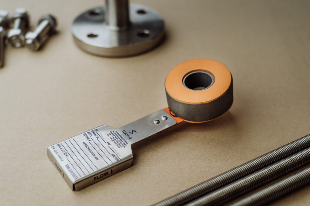
Two routes in API 520: coefficient of discharge and flow resistance
API 520 distinguishes two ways of treating a rupture disc in a sizing calculation. Which one applies depends mainly on how the disc is installed and what the relief path looks like.
The coefficient of discharge approach
In a simple installation the disc sits close to the vessel and discharges more or less directly to atmosphere through a short outlet. In that case the disc can be treated much like a nozzle. A fixed coefficient of discharge is applied to the minimum net flow area of the disc, and the calculation resembles the one used for a relief valve. It is quick and conservative, which is why many engineers like it. It is only valid when the installation stays within the geometric limits that API 520 sets for it, though, and those limits are easily exceeded once a longer inlet or discharge line is involved.
The flow resistance approach
In most process plants the disc is part of a longer relief path. There is an inlet nozzle, perhaps a short spool, the holder, the disc and a discharge line to a knock-out drum, a flare header or a safe location. In that case the disc is treated as one resistance in the system, just like an elbow or a length of pipe. The manufacturer determines a flow resistance factor for the disc and holder design by testing, and that factor is added to the resistances of all other components. The engineer then checks whether the whole line can pass the required flow with the available pressure difference. This is the more realistic view of rupture disc sizing in piping systems, and it shows clearly that a generous disc cannot compensate for an undersized discharge line.
When the disc sits in front of a relief valve
A third situation deserves attention. Many plants install a rupture disc directly upstream of a spring loaded relief valve, to keep the valve isolated from a corrosive medium or to stop leakage through the valve seat. In that combination the relief valve is usually the component that limits the capacity. The disc must then open fully and must not restrict the flow to the valve in a meaningful way. API 520 and the pressure vessel codes account for this with a capacity factor for the combination, based on tests or on a default value. The engineer also has to consider the space between disc and valve, because pressure that builds up there changes the pressure at which the disc opens.
Burst pressure, MAWP and overpressure in rupture disc sizing
Flow area is only half of the story. The other half is the pressure at which the disc opens, and how accurately it does so. The marked burst pressure is set by the manufacturer at a specified temperature, and every disc carries a tolerance around that value. The tolerance depends on the material and the manufacturing process, and it matters in two directions. At the upper end, the disc must still open before the equipment exceeds its allowed pressure. At the lower end, the disc must not open during normal operation.
In practice the burst pressure is usually chosen at or below the MAWP, so that even the highest possible burst pressure within the tolerance band keeps the equipment within its code limits. The relief flow is then calculated at the maximum relieving pressure, which is the burst pressure plus the permitted accumulation. Getting this sequence right is a core part of rupture disc sizing. A disc with the right area but the wrong burst pressure, or a burst pressure specified at the wrong temperature, is not correctly sized.
Temperature deserves a separate mention. The burst pressure of a disc depends on the temperature of the disc at the moment it has to open. At higher temperatures the effective burst pressure can drop, depending on material and design. That is why we ask for the normal operating temperature and the temperature in the relief scenario. A fire case, for example, can put the disc at a very different temperature than an ordinary day of production.
Holders designed to ASME Section VIII
Pressure calculations supplied with documentation
FEM analyses available on request
Exclusive STRIKO agent for the Benelux
Operating ratio: where rupture disc sizing meets disc type
The operating ratio describes how close the normal operating pressure sits to the burst pressure. It directly affects how long the disc lasts and how reliably it behaves. A disc that runs close to its burst pressure every day is worked harder than one with a comfortable margin, especially when the pressure cycles.
This is where the choice of disc type enters rupture disc sizing. Forward acting discs, with the pressure on the concave side, generally need a larger margin between operating pressure and burst pressure. Reverse acting or reverse buckling discs, loaded on the convex side, tolerate higher operating ratios and pressure cycling better, and holders for reverse buckling discs offer a lower risk of fatigue. Flat and multi-layer discs, domed discs with X or C scored domes, graphite discs and vacuum or double discs each have their own behaviour.
The practical consequence is simple. If the process runs close to MAWP, the burst pressure cannot be placed far above the operating pressure, and the operating ratio becomes tight. In that situation the disc type has to be chosen for that ratio, or the process conditions have to be discussed. We would rather have that discussion during design than after a disc has fatigued and opened during normal production. An unplanned opening is not just the cost of a new disc. It means a shutdown, possibly a release of medium, an investigation and a restart, all because a margin was chosen too tight on paper.
Gas, liquid and two-phase: what changes in the calculation
Gas service is the classic case for rupture disc sizing, and it is where most engineers feel at home. The flow through the disc is often choked, which means the mass flow depends mainly on the upstream relieving conditions and less on the back pressure. In a long discharge line that assumption can break down, which is another reason to use the flow resistance approach.
Liquid service behaves differently. Liquid flow is driven by the pressure difference across the relief path, and density and viscosity have a larger effect. Viscous liquids in particular can reduce the capacity of a relief path more than people expect. A familiar example is thermal expansion in a blocked-in section of pipe. A liquid that warms up in the sun or through tracing has nowhere to go, and a small relief flow is enough to protect the line. The required area is modest, but the burst pressure and the disc type still have to suit the operating conditions, because such a line may sit at a steady pressure for years.
Two-phase flow is the most demanding. Reactive systems, flashing liquids and foaming media can produce a mixture that needs a much larger flow area than a vapour-only calculation would suggest. Here the relief rate and the fluid properties usually come from a dedicated process safety study, and the rupture disc sizing follows those results. We support such studies with product data and can assist with HAZOP and safety studies, but the scenario analysis remains the responsibility of the plant owner and its engineers.
How Dutch Valve Vision supports rupture disc sizing
Dutch Valve Vision, based in Monster in the Netherlands, is the exclusive agent of STRIKO Verfahrenstechnik GmbH for the Netherlands, Belgium and Luxembourg. STRIKO has been active in rupture discs since 1974 and works to a philosophy of testing, evaluating and recalibrating. That philosophy is exactly what makes the burst pressure and the flow resistance of a disc reliable enough to build a sizing calculation on.
When an engineer brings us a rupture disc sizing question, we start from the process data. We need the medium and its composition, the operating pressure including peaks, the MAWP, the required burst pressure, the temperatures in normal operation and in the relief scenario, the required relief rate, any back pressure, the connection and the available installation space. With that information we select disc type, material and holder, and check the combination against the sizing basis.
Our holders are designed in line with ASME Section VIII, EN ISO 4126 and PED 2014/68/EU, and ATEX where applicable. They are supplied with material certificates to EN 10204 3.1, pressure calculations, inspection reports and traceability per component. On request we arrange FEM analyses and optimisation for cyclic loading. Standard metal discs are made of 316 stainless steel, with Hastelloy and titanium as options, and graphite discs are available from DN25 to DN400 for corrosive service. Dutch Valve Vision itself operates an ISO 9001 quality management system, certified by KIWA.
Mail your sizing basis to sales@dutchvalvevision.com or phone +31 (0)70-2210560 on weekdays from 09:00 to 17:00. We will go through your rupture disc sizing basis with you and come back with a disc and holder that fit it.
Specification ready? We will prepare a targeted quote.
Send us medium, pressure, temperature and connection. Our specialists come back with a matching proposal.
Frequently asked questions about rupture disc sizing
Question not listed? Our specialists are happy to help.
Which standard is used for rupture disc sizing?
For many projects the reference is API 520, the recommended practice for sizing, selection and installation of pressure relieving devices. It is widely used in refining, petrochemicals and other process industries. For pressure vessels built to ASME Section VIII, the code requirements for overpressure protection apply alongside it. In Europe, EN ISO 4126 is the family of standards for safety devices, including bursting discs. The project specification usually states which framework governs. Sometimes both appear, for example in a European plant with American licensor documents. We can work with either basis. Please tell us which one applies when you send your request.
What is the difference between the coefficient of discharge method and the flow resistance method?
Both methods answer the same question, namely whether the relief path can pass the required flow. The coefficient of discharge method treats the disc like a nozzle and applies a fixed coefficient to its minimum net flow area. It is only valid for simple installations that stay within the geometric limits set by API 520. The flow resistance method treats the disc and holder as one resistance in the complete relief line. The manufacturer determines that resistance by testing the design. All pipe sections, fittings and the disc are then combined in one hydraulic calculation. This method is more realistic for longer inlet and discharge lines. Most process installations end up with the flow resistance method.
Can I size a rupture disc on the pipe diameter alone?
No, the nominal diameter says nothing about whether the relief flow will fit. Sizing has to start from the required relief rate in the governing scenario. A disc chosen on the available pipe size can be too small, which is unsafe. It can also be much larger than needed, which increases reaction forces and cost. The relief rate depends on the medium, the scenario and the relieving conditions. Once that rate is known, the disc area and the whole relief path are checked against it. We always ask for the relief rate before we propose a diameter. If that rate is not yet available, we can discuss which scenarios need to be defined first.
How does MAWP affect the choice of burst pressure?
The MAWP sets the upper limit that the protected equipment may normally see. The burst pressure is usually chosen at or below the MAWP. The tolerance of the disc must also be taken into account, so that even the highest burst pressure in the band keeps the equipment within its code limits. During relief, the pressure is allowed to rise above MAWP by a permitted overpressure. The relief flow is calculated at that maximum relieving pressure. A burst pressure that is set too high therefore eats into the margin available for flow. Setting it too low can cause the disc to open during normal operation. The right value sits between those two limits, and the operating ratio of the chosen disc type decides how much room there is.
What is the operating ratio and why does it matter for sizing?
The operating ratio describes how close the normal operating pressure sits to the burst pressure. A disc that runs close to its burst pressure is loaded more heavily every day. With pressure cycling, that can lead to fatigue and an early opening. Forward acting discs generally need a larger margin than reverse acting discs. Reverse buckling designs tolerate higher operating ratios and cycling better. If the process runs close to MAWP, the operating ratio becomes a design constraint. In that case the disc type has to match the ratio. We check this for every request.
Does temperature change the result of a rupture disc sizing calculation?
Yes, in two ways. First, temperature affects the fluid properties used to calculate the relief rate and the flow through the disc. Second, it affects the burst pressure of the disc itself. At higher temperatures the effective burst pressure can drop, depending on material and design. A fire case can therefore put the disc in a very different situation than normal production. That is why the burst pressure is always specified at a temperature. We ask for both the normal operating temperature and the temperature in the relief scenario. Without the second value, a sizing basis is incomplete.
Is two-phase flow covered by a normal rupture disc sizing calculation?
Not by a simple gas or liquid calculation. Two-phase flow from reactive systems, flashing liquids or foaming media can require a much larger flow area. The relief rate and fluid properties for such cases usually come from a dedicated process safety study. The rupture disc sizing then follows from those results. Using a vapour-only calculation for a two-phase case can lead to a seriously undersized relief path. We support these studies with product data and can assist during HAZOP and safety reviews. The scenario analysis itself stays with the plant owner and its engineers. Please share the study basis when you contact us.
What information does Dutch Valve Vision need to help with sizing?
We need the medium and its composition first. Next come the required relief rate, the operating pressure including peaks, the MAWP and the required burst pressure. We also need the temperature in normal operation and in the relief scenario. Any back pressure from a discharge system should be included. The connection, the nominal diameter and the available installation space complete the picture. For a replacement, the existing tag data and specification help us to start quickly. The more complete the data, the fewer questions we need to ask before we can advise. Send everything to sales@dutchvalvevision.com and we will review it with you.
Check your rupture disc sizing with us
Send us the medium and composition, relief rate, operating pressure including peaks, MAWP, required burst pressure, temperatures and connection size. We review the data with you and propose a matching STRIKO disc and holder.
- +31 (0)70-2210560
- sales@dutchvalvevision.com
- Vlotlaan 641, 2681 TZ Monster, the Netherlands
- Mon-Fri 09:00-17:00