
Rupture disc sizing calculator
Which inputs a rupture disc sizing calculator needs, why its answer is only a first step and how we work through the numbers with you.

A rupture disc sizing calculator estimates the flow area a disc needs from a handful of inputs: the medium and its phase, the required relief rate, the set pressure and allowable overpressure, the relieving temperature and the back pressure. Its answer is only a first step, because disc type, tolerance, operating ratio, holder and the resistance of the whole relief path still have to be checked. Dutch Valve Vision reviews those inputs with you and translates them into a STRIKO disc and holder.
- What a rupture disc sizing calculator can and cannot do
- The inputs a rupture disc sizing calculator needs
- Why a rupture disc sizing calculator is only a first step
- What the calculator does not see
- Typical input errors and how to avoid them
- From calculator result to a disc you can order
- Let us work through the calculator inputs with you
Unsure about the right choice?
Share your process data with our specialists. We check the numbers with you and give reasoned advice.
What a rupture disc sizing calculator can and cannot do
A rupture disc sizing calculator is usually the first tool an engineer opens when a relief device has to be specified. It is quick, it gives a number and it feels like progress. Enter a medium, a flow and a pressure, press a button and a required area or a nominal diameter appears. For a first estimate during a feasibility study, that is genuinely useful.
Picture a project engineer the evening before a design review. The P&ID shows a rupture disc on a new buffer vessel, and the review team will want to know whether the nozzle size is realistic. A rupture disc sizing calculator gives a quick answer, and the engineer walks into the meeting with a diameter. The next morning someone asks which relief scenario that diameter covers, what temperature the disc will see in a fire case and what happens to the capacity with a long discharge line to the flare knock-out drum. The calculator did not ask those questions, so the answer is not there.
That is the honest position of any rupture disc sizing calculator. It does the arithmetic well, but it can only work with what it is given, and it knows nothing about the installation around the disc. We do not offer an online calculator on this page, and that is a deliberate choice. What we offer instead is to go through the inputs with you and to turn the result into a disc and holder that can actually be manufactured, tested and installed. The request form below this page is the place to start.
The inputs a rupture disc sizing calculator needs
Every calculator, whether it is a spreadsheet, a web tool or part of a process simulation package, depends on the same core inputs. Knowing what each of them means, and where it comes from, is more important than the tool itself.
Medium and phase
The first input is the medium, and with it the phase at relieving conditions. Gas, vapour, liquid and two-phase flow are calculated in different ways. For a gas or vapour the calculator needs the molecular weight, the ratio of specific heats and the compressibility. For a liquid it needs density and viscosity. A medium that is liquid in the vessel but flashes as the pressure drops through the disc is neither, and a simple calculator will usually not handle it correctly.
Required relief rate
The relief rate is the flow that has to leave the system in the governing scenario, usually expressed as a mass flow. It is not a property of the disc or the pipe. It comes from a relief study that looks at blocked outlets, cooling failures, external fire, control valve failure and, in reactive systems, runaway reactions. If this input is guessed, every result that follows is a guess too.
Set pressure and allowable overpressure
The calculator needs the pressure at which the disc should open and the maximum pressure allowed during relief. The first is linked to the burst pressure you will specify for the disc. The second follows from the maximum allowable working pressure of the protected equipment and the overpressure the pressure vessel code permits above it, which is larger for a fire case than for ordinary operating upsets. The flow is calculated at that maximum relieving pressure.
Relieving temperature
Temperature affects both the fluid properties and the disc. The relieving temperature determines the density of a gas and the viscosity of a liquid at the moment of relief. It also affects the burst pressure of the disc itself, which can drop at higher temperatures depending on material and design. A calculator that only asks for one temperature is only giving half the picture.
Back pressure and the outlet system
Finally there is the pressure on the outlet side of the disc. Superimposed back pressure from a flare header or collection system is present before the disc opens. Built-up back pressure develops once flow starts. A rupture disc responds to the pressure difference across it, so back pressure changes the effective opening pressure as well as the flow. For long discharge lines, a rupture disc sizing calculator that treats the disc as an isolated nozzle will overestimate capacity.
Geometry of the relief path
More advanced tools also ask for the layout of the relief path. That means the length and diameter of the inlet piping, the number and type of fittings, the length of the discharge line and where it ends. With those inputs the tool can treat the disc as one resistance among many, which is how API 520 describes the flow resistance approach. Without them, the result assumes an ideal installation that seldom exists in a real plant. If you do not yet know the final routing, a conservative estimate is better than leaving the fields empty.
Why a rupture disc sizing calculator is only a first step
Once the numbers are in, the calculator gives an area. That area is necessary, but it is not a specification. Several decisions still lie between the calculated area and a disc that can be ordered.
The first is the disc type. Forward acting discs, reverse acting discs, flat and multi-layer discs, domed discs with X or C scored domes, graphite discs and vacuum or double discs all behave differently. The type determines how close the operating pressure may sit to the burst pressure, how the disc copes with pressure cycling and whether it is suitable for the medium.
The second is the burst pressure and its tolerance. Every disc is made for a precise burst pressure at a specified temperature, with a tolerance that depends on material and manufacturing. The calculator treats the set pressure as one exact number. In reality it is a band, and both ends of that band must be checked against the operating pressure and the allowable pressure.
The third is the resistance of the complete relief path. In most plants the disc is not an isolated nozzle but one element in a line with an inlet nozzle, a holder and a discharge pipe. The flow resistance of the disc and holder, which the manufacturer determines by test, is added to the resistance of the pipe and fittings. A rupture disc sizing calculator that ignores the piping can suggest a disc that looks adequate but cannot deliver the flow in the real installation.
The fourth is the holder and the material. Temperature, corrosion, vibration and cyclic loading all influence which holder design and which material make sense. None of that comes out of a sizing formula, yet all of it affects whether the disc will perform as calculated.
What the calculator does not see
Some of the most important questions about a rupture disc never enter a sizing formula. Pressure cycling is one of them. A disc on a batch reactor that is pressurised and vented several times a day is loaded very differently from a disc on a storage vessel that sits at a constant pressure for months. The area may be identical, but the right disc type and the right operating ratio are not.
Vacuum is another. A vessel that is emptied quickly or cools down after steam cleaning can pull a vacuum on the process side of the disc. A disc that is not designed for that can be pulled the wrong way and damaged. Vacuum support, vacuum suitable discs or double discs, and vacuum support holders, prevent that, yet none of this shows up in a calculator result.
Corrosion and deposits complete the list. An aggressive medium can thin a metal disc over time and lower its burst pressure, while polymerising or crystallising media can build up on the disc and change its behaviour. Material choice, coatings such as TFE on graphite discs, and in some cases a different disc type are the answer. These are exactly the points we raise when we review calculator inputs with an engineer.
Selection needs medium, pressure and temperature
Pressure calculations included with holder documentation
Engineering support for disc and holder
Exclusive STRIKO agent for the Benelux
Typical input errors and how to avoid them
Calculators rarely make arithmetic mistakes. People make input mistakes, and a few of them come back again and again in practice.
Sizing on the pipe diameter is the most common. An engineer enters the existing nozzle size and checks whether it is enough, rather than starting from the relief rate. That can work, but only if the relief rate is known and correct. Using normal operating temperature instead of relieving temperature is the second. A fire case can raise the disc temperature far above normal, and the burst pressure and fluid properties shift with it.
Forgetting back pressure is the third. A disc that discharges into a header shared with other relief devices may see a significant pressure on its outlet, and that pressure has to be part of the calculation. Mixing units is the fourth, especially gauge and absolute pressure, and it produces errors that look plausible at first glance. The fifth is treating a two-phase relief as gas-only, which can lead to a seriously undersized relief path.
A maintenance planner who inherits a sizing spreadsheet from a predecessor faces a special version of this risk. The formulas may be sound, but the assumptions built into the cells are invisible. When the process has changed since the sheet was made, the output can be wrong without anyone noticing. A quick review of the assumptions, one cell at a time, is often the most valuable hour spent on a replacement project.
From calculator result to a disc you can order
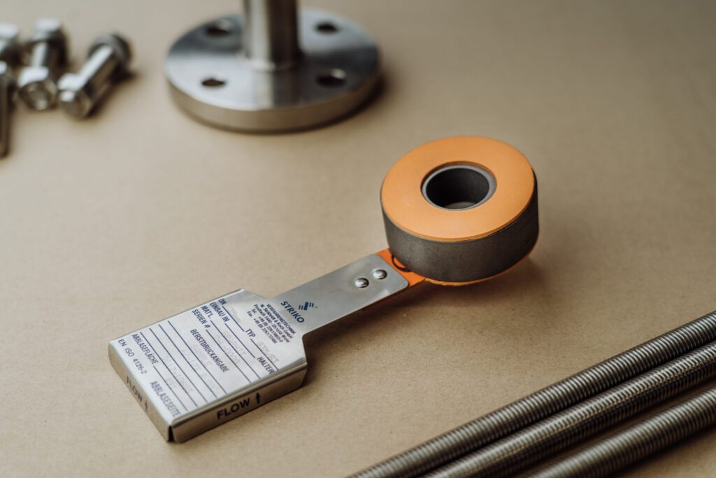
Moving from a rupture disc sizing calculator result to a purchase order is where most of the engineering happens. The calculated area becomes a nominal size that fits the connection standard, whether DIN or ANSI flanges. The set pressure becomes a burst pressure at a specified temperature, with a tolerance the manufacturer can guarantee. The medium and temperature lead to a material choice. Our standard metal disc is made of 316 stainless steel, with Hastelloy and titanium as options, and graphite discs from DN25 to DN400 cover strongly corrosive service.
The holder follows. Forward acting holders, reverse buckling holders and vacuum support holders are available in carbon steel, 316/316L stainless steel, duplex and super duplex, and Inconel or Hastelloy. Our holders are designed in line with ASME Section VIII, EN ISO 4126 and PED 2014/68/EU, and ATEX where applicable, and are supplied with material certificates to EN 10204 3.1, pressure calculations, inspection reports and traceability. Burst detection with an electrical loop or magnetic sensor can be added to signal an opening to your control system.
At this point the calculation is checked again against the final choice. The flow resistance of the chosen disc and holder replaces any assumed value, the operating ratio is confirmed for the selected disc type and the documentation is prepared for your design file.
Let us work through the calculator inputs with you
Dutch Valve Vision is the exclusive agent of STRIKO Verfahrenstechnik GmbH for the Netherlands, Belgium and Luxembourg. STRIKO has been active in rupture discs since 1974 and works to a philosophy of testing, evaluating and recalibrating, which is exactly what gives the burst pressure and flow data behind any rupture disc sizing calculator their meaning.
Rather than a web tool, we offer a conversation. Use the request form below this page to send us the medium and its composition, the required relief rate, the operating pressure including peaks, the required burst pressure, the temperature in normal operation and in the relief scenario, any back pressure, the connection and the installation space. If you have already run a rupture disc sizing calculator, include the result and the assumptions behind it. We go through the inputs with you, flag anything that looks inconsistent and propose a STRIKO disc and holder that match the sizing basis. For demanding cases we can arrange FEM analyses on request and support HAZOP and safety studies.
You can also reach us at sales@dutchvalvevision.com or on +31 (0)70-2210560, Monday to Friday from 09:00 to 17:00. Dutch Valve Vision works with an ISO 9001 certified quality management system, certified by KIWA.
Specification ready? We will prepare a targeted quote.
Send us medium, pressure, temperature and connection. Our specialists come back with a matching proposal.
Frequently asked questions about rupture disc sizing calculator
Question not listed? Our specialists are happy to help.
Does Dutch Valve Vision offer an online rupture disc sizing calculator?
No, we deliberately do not publish an online calculator. A calculator can only work with the inputs it receives, and the most important decisions lie outside it. We prefer to review the inputs with you and turn them into a real disc and holder specification. You can use the request form below this page to send us your data. If you have already used a calculator, send the result along with the assumptions. We will check them against the disc types and holders available from STRIKO. That gives you a result that can actually be ordered. It also gives you documentation for your design file.
Which inputs does a rupture disc sizing calculator need?
The core inputs are the medium and its phase, the required relief rate, the set pressure and the allowable overpressure. The relieving temperature is needed as well, because it affects the fluid properties and the disc. Back pressure on the outlet side has to be included. For a gas, the molecular weight, ratio of specific heats and compressibility are required. For a liquid, density and viscosity matter. For longer relief lines, the geometry of the inlet and outlet piping is also needed. Without these inputs the result is only a rough estimate. We ask for the same data when you send us a request.
Why can a calculator result differ from the final disc size?
A calculator usually treats the disc as an isolated nozzle with an exact set pressure. In reality the burst pressure has a tolerance and is specified at a temperature. The disc also sits in a relief path with its own flow resistance. The chosen disc type may change the operating ratio and therefore the burst pressure. The final nominal size has to fit a standard DIN or ANSI connection. Each of these steps can move the final size away from the first estimate. That is normal and not a sign that the calculator was wrong. It simply shows that sizing continues after the first number appears.
Where does the relief rate for the calculator come from?
The relief rate comes from a relief study of the process, not from the disc or the pipe. That study looks at scenarios such as blocked outlets, cooling failure, external fire and runaway reactions. Each scenario gives its own relief load. The governing scenario sets the rate used for sizing. In reactive or flashing systems, the relief may be two-phase, which needs a specialised assessment. If the relief rate is estimated rather than calculated, every result that follows is uncertain. The plant owner and its engineers are responsible for defining the scenarios. We can support that work with product data and in HAZOP and safety studies.
How does back pressure affect the calculator result?
A rupture disc responds to the pressure difference across it. Back pressure on the outlet side therefore raises the process pressure needed to burst the disc. It also reduces the pressure difference available to drive the flow. Superimposed back pressure from a header is present before the disc opens. Built-up back pressure develops once the medium starts to flow. A calculator that ignores both can overestimate capacity and underestimate the opening pressure. For discs discharging into shared systems, this effect can be significant. Always include the expected back pressure in the inputs you send us.
Can a sizing calculator handle two-phase flow?
Most simple calculators are designed for single-phase gas or liquid flow. Two-phase relief from reactive systems, flashing liquids or foaming media behaves very differently. It can require a much larger flow area than a gas-only calculation suggests. Dedicated methods and process safety software are normally used for these cases. The results of that work then become the basis for disc selection. Using a single-phase calculator for a two-phase case is one of the more serious sizing errors. If your case may be two-phase, mention it clearly in your request. We will then ask for the study results rather than a single relief rate.
What happens after I send my calculator inputs to Dutch Valve Vision?
We first check whether the inputs are complete and consistent. Where data are missing, we ask targeted questions instead of making assumptions. Then we look at the disc type that suits your operating ratio, medium and pressure profile. Next we select a material and a holder that fit the temperature and the connection. The flow resistance of the chosen disc and holder is used to check the sizing basis again. Finally we prepare a proposal with the relevant documentation. Holder documentation includes material certificates to EN 10204 3.1, pressure calculations and inspection reports. You then have a specification you can review and approve.
Is a calculator result enough for a replacement disc?
For a like-for-like replacement with a confirmed design basis, the original specification is usually the best reference. A new calculation is only needed when the process, the medium or the equipment has changed. The existing tag data, the burst pressure, the temperature and the holder type are the starting point. Many older plants have made process changes without updating the relief basis. In that case a quick check with a calculator can reveal whether the old disc still fits. If the result differs from the installed size, the relief study should be reviewed. We can help identify which data need to be updated. Send us the existing tag data and we will take it from there.
Send us your calculator inputs
Use the form below this page to send the medium, relief rate, set pressure, temperatures, back pressure and connection. We check the inputs with you and come back with a matching STRIKO disc and holder.
- +31 (0)70-2210560
- sales@dutchvalvevision.com
- Vlotlaan 641, 2681 TZ Monster, the Netherlands
- Mon-Fri 09:00-17:00